

The plastic covers were quickly taken care of by a little plastic primer. I still had a cheap can of matte-black spray paint. Surely I don’t have to explain what a spray paint can is… Ok, it’s a cylindrical can with paint and aerosol inside and… oh, never-mind.
Anyhow, after painting the plastic black, they matched the brushed aluminum (really, what was Iomega thinking with a beige and black color scheme?). Now it’s time to tackle the “always on” issue. I have a background in electronics, but even a novice can figure this out.
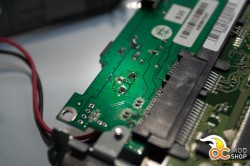
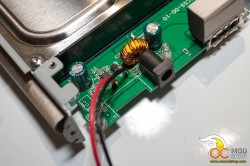
Remove resistor and solder power wires
I figured the manufacturer uses the same electrical board for a wide range of enclosures and there must be a place for a power switch somewhere on the PCB.
I need to remind you I wrote this after I already modded the enclosures so I’m missing some images in between but you should get the point.
Adding a power switch
I examined the board and paid particular attention to the area around the power connector. A quick measurement with a volt meter revealed a large area that also have trough holes that were soldered closed. Crossing the two pads was a small 1-Ohm SMD resistor.
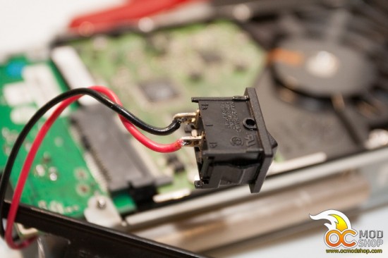
I de-soldered the resistor and plugged in the board and noticed the LED did not turn on. When I shorted the 2 trough holes (now disconnected via the SMD) I saw the board power up.
SUCSESS! (or Kaplah! for our Klingon readers)
The rest is child’s play really. Now that we have the on/off part of the board working it is a simple matter of wiring a little power switch. I grabbed two switches from my box o’ stuff and measures its size to make a hole in the aluminum part of the enclosure.


