

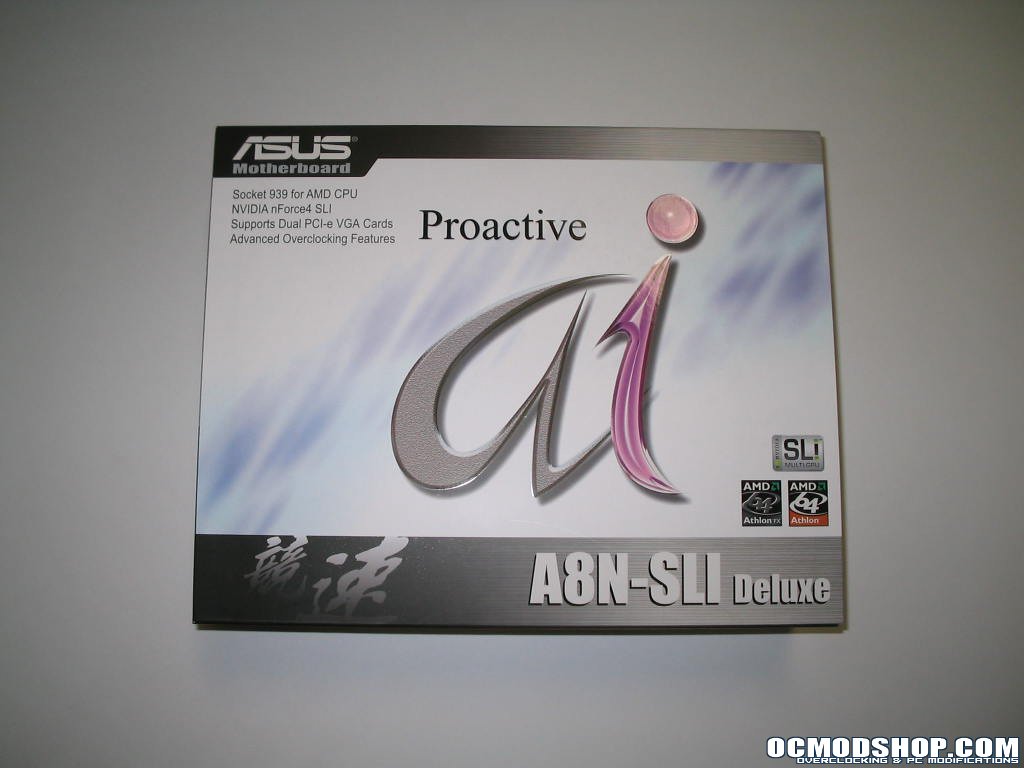
The motherboard comes in a very clean looking and eye catching box with a glossy and satin finish. The front sports the Asus AI logo, for their proprietary motherboard overclocking. On the back there are descriptions of the boards feature set and a section for Asus’ AI suites “proactive features”. There is also a flip up portion which contains more and more descriptions of the board’s components, layout and bundled AI software. I can attest, if you picked this box up off the shelf, you’d have every question answered about this board short of, “Hw many FPS in my favorite game am I going to get?” Nice job Asus.
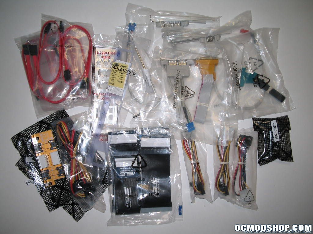
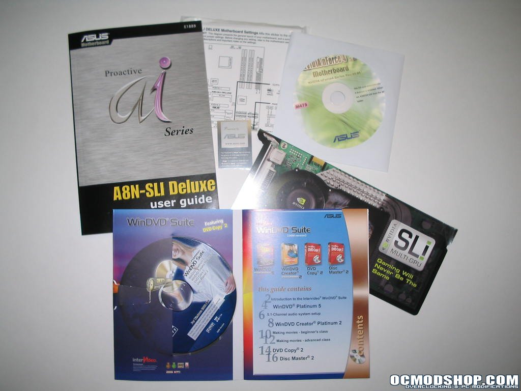
Inside of the box I was surprised as to the sheer amount of accessories included. Being a minimalist, I really didn’t know what to do with them all, but I’m sure many of you think the more the better. Here is the complete list of accessories: SLI connector, 1 x 1-port IEEE1394 module, 1 x SLI retention bracket, 8 x Serial ATA cables, 1 x SATA Extension module for external devices, 4 x 2-port SATA power cable, 1 x 2-port USB2.0 / Game module, 1 x 2-port USB2.0 module, 1 x COM Port, module, 1 x UltraDMA 133/100/66 cable, 1 x IDE cable, 1 x FDD cable, 1 x I/O Shield, User’s manual, Instant Music, Setting Sticker, and WinDVD Suite
Some key accessories of note are the Serial ATA extension module and the SLI accessories. The Serial ATA extension module lets you access two of your SATA connectors through a PCI slot. That way you can connect two SATA externally if you need a quick file swap, or need to test a HD and don’t want to mount it permanently in your case. The SLI accessories include the SLI bridge connector which links two identical graphics cards for SLI operation, and Asus even included a hold down to make sure the connector doesn’t fly off during transport.
Board Layout
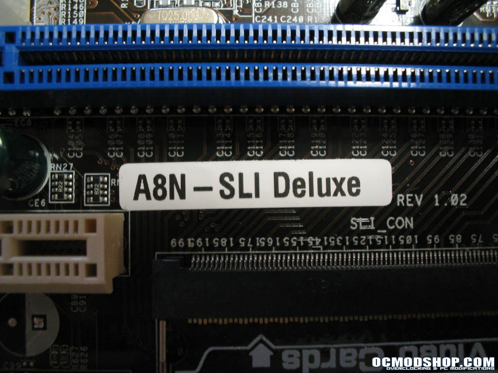
The board layout overall is pretty good, Asus used a sleek black PCB and the followed a more traditional AMD layout. The CPU socket is centered on the right with the power MOSFET’s behind the I/O connectors and the ram slots are parallel to the bottom edge of the board (unlike parallel to the right side like some nForce3 boards). You can see that this board is a Revision 1.02, so there were very minimal hardware changes done before the board hit store shelves. Capacitors on the board are from several manufacturers: Rubycon, Taiwan Ostor and KMG.
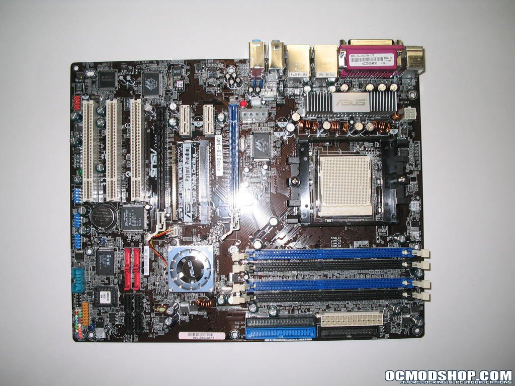
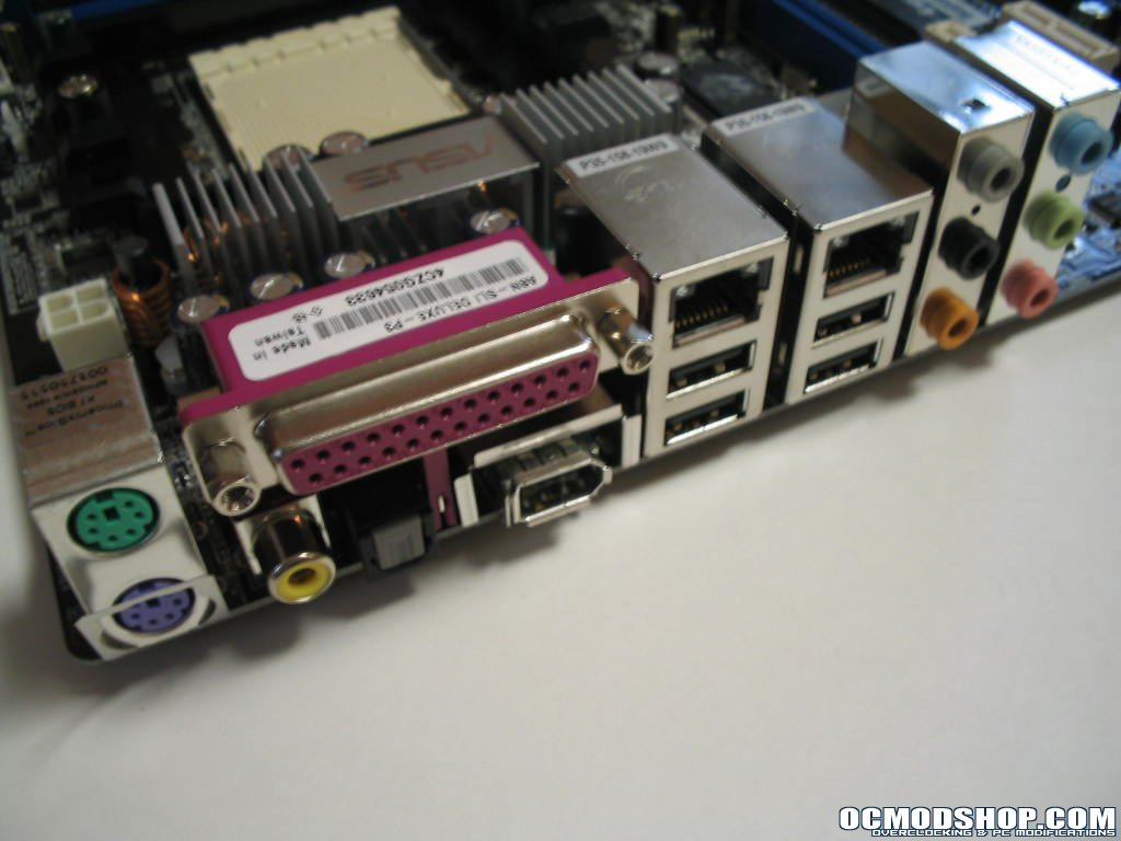
The back I/O panel contains the following ports, from left to right: PS/2 Keyboard and Mouse, RCA and SPDIF Digital audio, Parallel port, IEEE1394 Firewire, Marvell PCI Gigabit LAN, nVidia Gigabit LAN, 4xUSB 2.0 and 6 analog audio mini-jacks. Behind the I/O ports you can see that Asus chose to place an aluminum heatsink on the MOSFET’s that feed the various power hungry components on this board. The heatsink is roughly 5/8”x3/4”x4” and is mounted using spring push pins. Underneath there is a hefty amount of white heatsink compound and each MOSFET makes good contact with the heatsink.
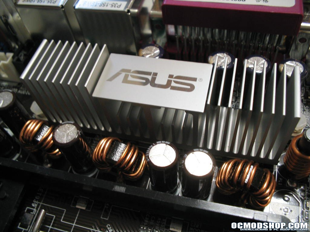
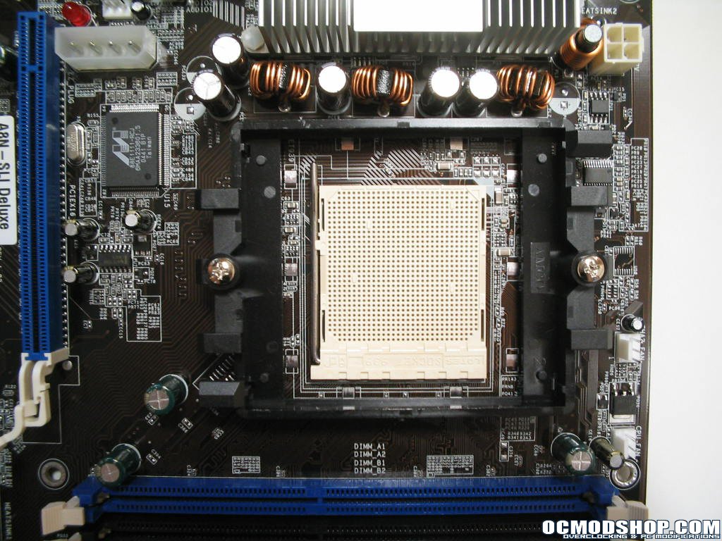
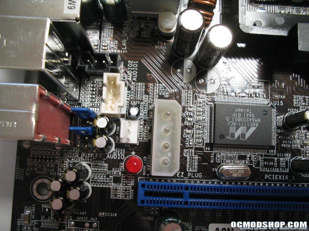
Asus engineers did a good job of keeping the CPU socket area rather clutter free. The only issues you may run into is if you have a cooler mounting that extends beyond the stock LOTES bracket; it could come into contact with the components on the upper edge of the stock bracket. Another is if you have a large heatsink that require tipping to mount, such as the Thermalright XP90 and XP120. A Thermalright XP90 was used in this review, and there is a possibility of hitting the MOSFET heatsink depending on how you orient the heatsink. To the right of the CPU socket is the Auxiliary 4-pin 12v connector, in a location I feel is more preferred. Up and out of the way. To the left of the CPU socket you can see the accessory Marvel Gigabit LAN controller and the Asus EZ Plug Molex connector. This plug supplies auxiliary power to the PCI-Express x16 slots for use during SLI mode. PCI-Express requires 75watts of power for the graphics subsystem, so with two graphics cards this can put heavy stress on the board’s power lines. The plug also has an indicator light to remind you to plug a connector in when in SLI mode. This assures there is no lack of power when both cards are fully utilized. The only issue I see here is that Asus placed this connector in a very tight spot once you have cards, chip and heatsink mounted.
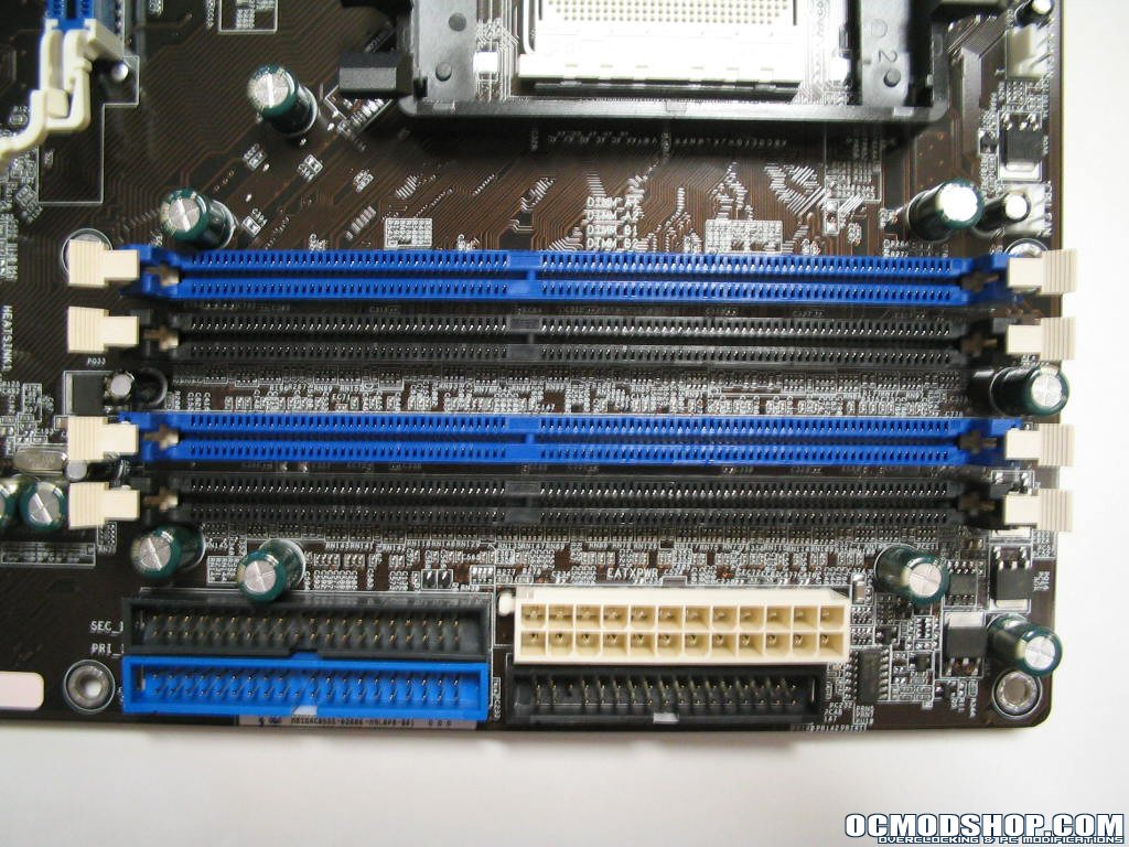
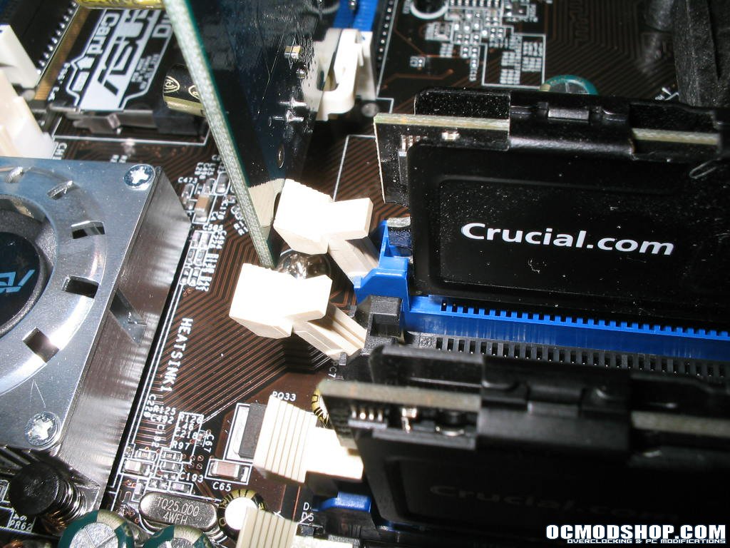
In the lower right of the board are the ram slots, IDE connectors, Floppy connector and the 24-pin ATX. This board can accept both the 24-pin ATX and 20-pin ATX power supplies. So if you find yourself with a good or brand new 20-pin ATX power supply, there’s no need to rush out and buy a 24-pin. Great feature. The ram slots on this board are color coded to designate which slots to use for dual channel operation. In this case use both blue slots to run two memory modules in dual channel. One major layout snag you can see here however is the fact that those with longer cards may run into the all to common problem of the clips hitting the graphics card PCB. This can make removing ram a pain with a graphics card installed.
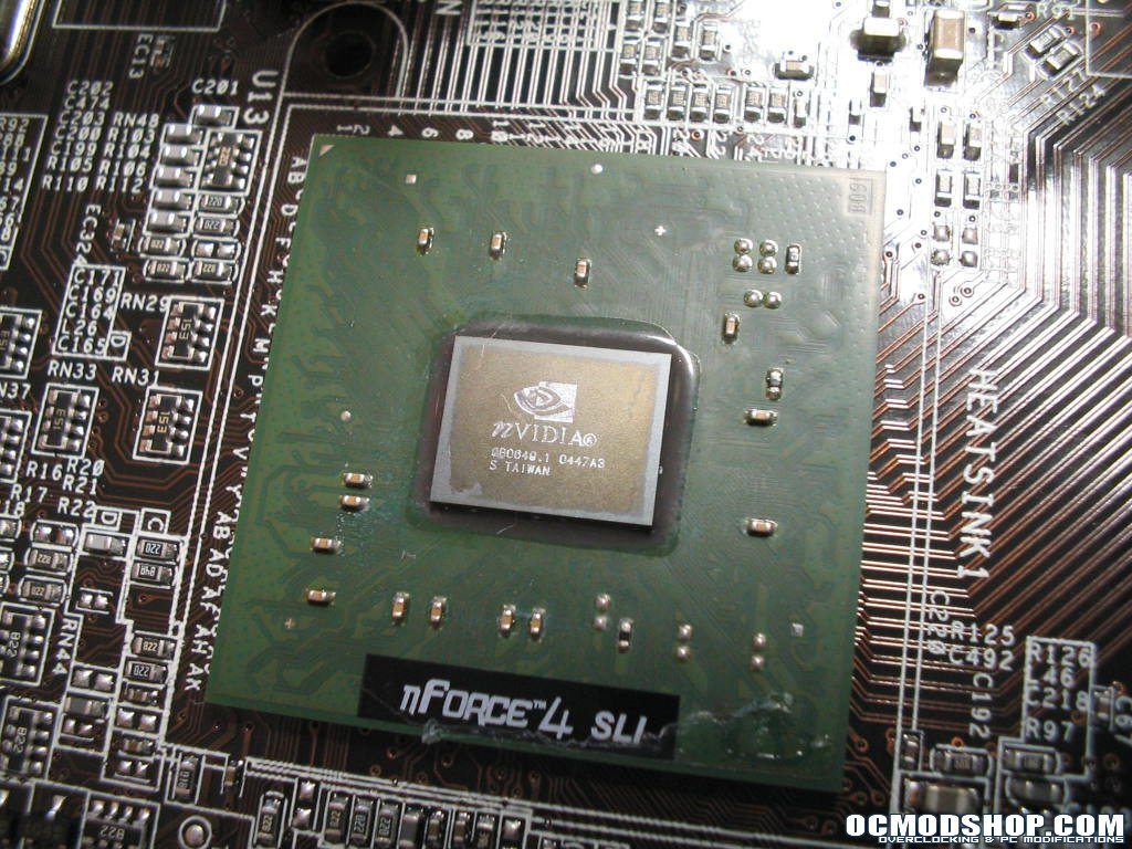
To the left of the memory slots in the lower left, you can see the nForce4-SLI chipset, the SATA connectors, Silicon Image 3114R SATA-RAID controller, CMOS battery and reset jumper, BIOS chip, I/O and game port headers, and 3x USB2.0 connectors. The nForce4-SLI chipset has been covered with a small, chrome, actively cooled heatsink mounted with push-pins that puts out mildly noticeable noise. Underneath you can see the bare nForce4-SLI chipset. Asus used a thin plastic spacer to cover the capacitors around the chipset and a dark gray, putty like thermal interface material along with a small amount of white thermal grease. This board offers a grand total of 8 SATA connectors across two RAID controllers. The black connectors are associated to the chipset based NVRAID, the red connectors are associated to the accessory Silicon Image RAID controller.
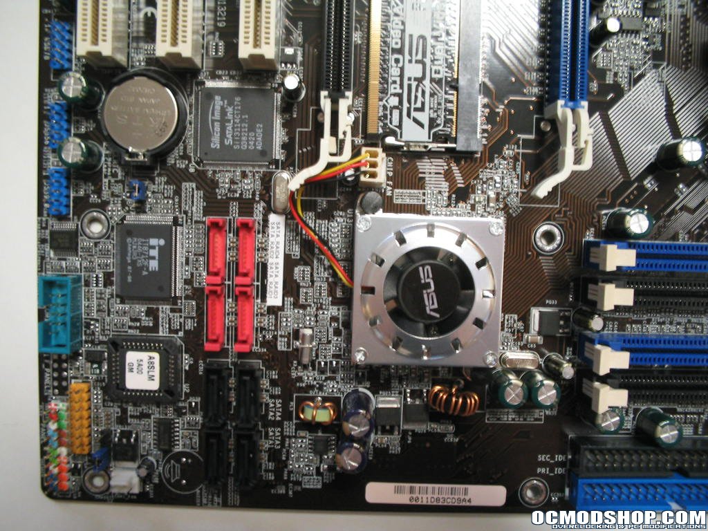
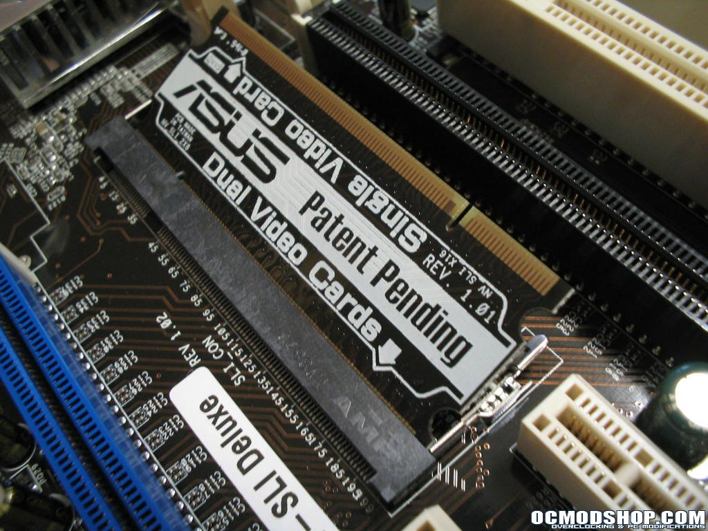
In the upper left of the board you will find a blue and a black PCI-Express x16 slots, 2x PCI-Express x1 slots, the ASUS SLI EZ-Selector slot, the ALC850 audio codec chip (just above the rightmost PCI-Express x1 slot), 3x PCI slots, an IEEE-1394 Firewire connector and the motherboard power status LED. The x16 PCI-Express slots are used for graphics cards and are color coded for primary card (blue) and secondary (black). All video output is utilized through the primary x16 slot regardless of whether you are using SLI or not. Currently to utilize SLI, motherboards have to have a physical switch to split the PCI-Express x16 graphics channel across two x16 slots, thereby splitting one x16 into two x8 channels, one for each card. Asus uses a special bridge they call the SLI EZ-Selector. They use a unique design that takes advantage of a SODIMM slot common to most laptop memory. Just release the clips and the EZ-Selector pops up at a 45 degree angle. Remove the selector PCB and re-insert it in its respective orientation to select either single or dual video card operation. Asus has a patent pending for this design using existing technology for a unique use. This method is very easy to use and should definitely cut down on the number of RMA’s for broken SLI selector cards.
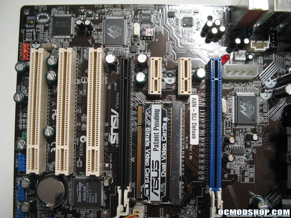
One good thing I notice right off the bat is the fact that Asus allowed for two x1 PCI-Express between the SLI video card slots. This gives those using 2-slot video cards or wanting to fit a water block and tubing between the cards plenty of wiggle room. It also allows for a better thermal design as the primary card won’t be hindered by the secondary card being right up against it.

