
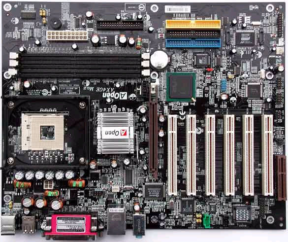
This motherboard is boxed in standard cardboard with a print of the product on the front. Included with thte board is a black floppy cable, a black ATA100 cable as well as a yellow ATA133 cable and red Serial ATA cable. Also included is the S/PDIF header and bracket, 2 FireWire ports, 2 USB 2.0 ports, a rear I/O plate and installation CDs. Of course you also get a pull-out installation guide and manual.
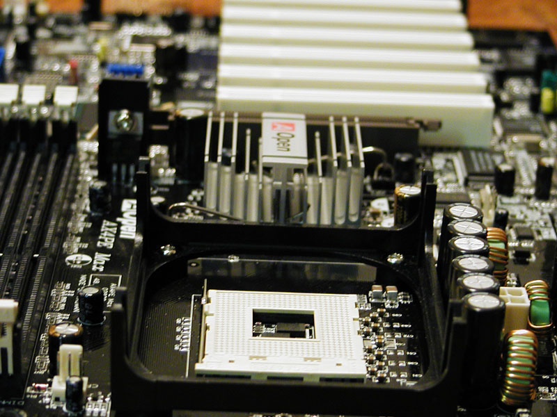
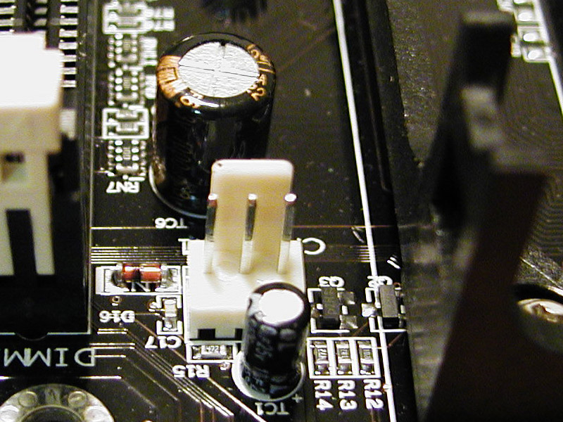
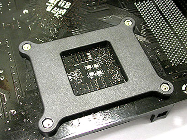
The board layout is fairly well though out, but there are a few areas of concern. The CPU area has been crowded with the Northbridge, power regulation circuit, and ATX12V header. Heatsink airflow could be impeded if the snaking 12V power cable is not tucked away. I did have a more difficult time maneuvering the heatsink clips into place. Some of the more monstrous heatsinks may have to be removed if the 12V line needs to be unplugged. The CPU retention mechanism is a very hard plastic, and is reinforced on the underside of the board, so the board will not warp under the stress of any retention clip.
Like many motherboards, the AGP slot is in close proximity to the DIMM slots, sometimes requiring video card removal when installing memory. The AGP port is protected by a circuit that automatically detects the voltage of the AGP card and prevents the chipset from being burnt out. If a 3.3V AGP card is used, a special LED will light up on the motherboard to warn you of possible damage.
Six 3300Mfds and three 2200Mfds capacitors have been placed around the CPU socket. These are much larger than capacitors used on cheaper motherboards (1500Mfds) and offer greater power stability. The voltage regulation circuits are triple phase and bi-Mosfet. This provides very clean power to the processor, with little dips or jumps to maximize stability. This is just one of the little unmentioned features that attributes to the overall quality of the board.
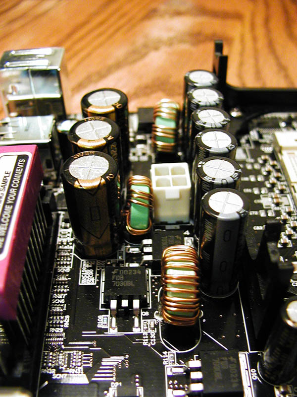
The layout of the motherboard implements AOpen’s design methodology they call a “Frequency Isolation Wall”. Basically certain trace leads on the motherboard are lengthened to avoid cross-talk and frequency interference between different regions of the motherboard. Looking at the board, you can see that some traces seem unnecessarily long and seem to waste space, but this is actually by design. The trace length and route is calculated so that clock skew will be controlled to within a pico-second (1/1012 sec). This is just another example of the thought and care that has gone into this board’s development.
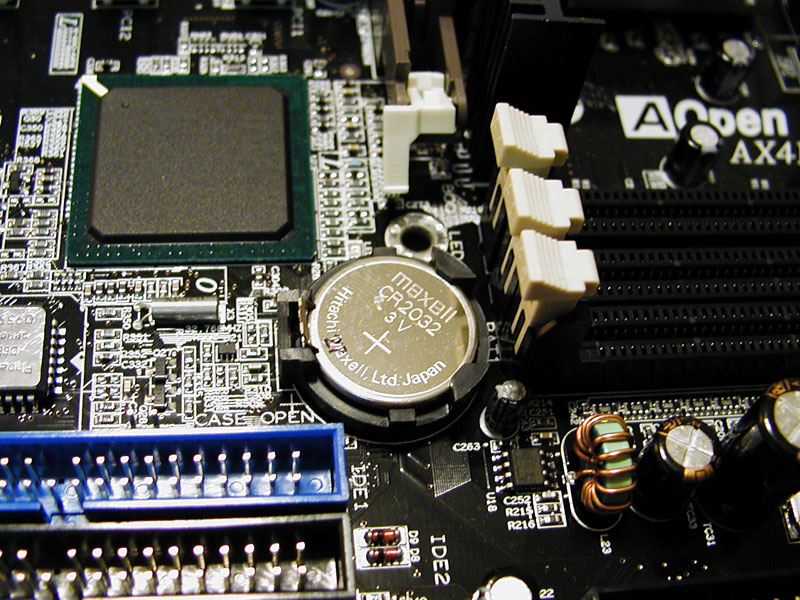
The motherboard implements a special circuit that allows you to save your current CPU and CMOS Setup configurations without the need for a battery. The real time clock can also keep running as long as the power cord is plugged in. Basically the onboard battery isn’t used until the power cord is unplugged, thus saving battery life.
The motherboard has two tiny but bright red LEDs called the STBY and BOOT LED. These STBY LED will light up when power is provided to the motherboard, which can be a convenient power indicator when the computer is in standby mode. The BOOT LED will blink while the system is in POST, and then remains steady if everything is ok.
The board’s northbridge chip (the Intel 845PE chipset) is passively cooled, with the standard Intel rentention mechanism. The retention mechanism is sturdy, yet allows for easy heatsink removal. The heatsink uses a thermal pad for heat transfer, and I would advise replacing this with a bit of thermal compound of some sort.
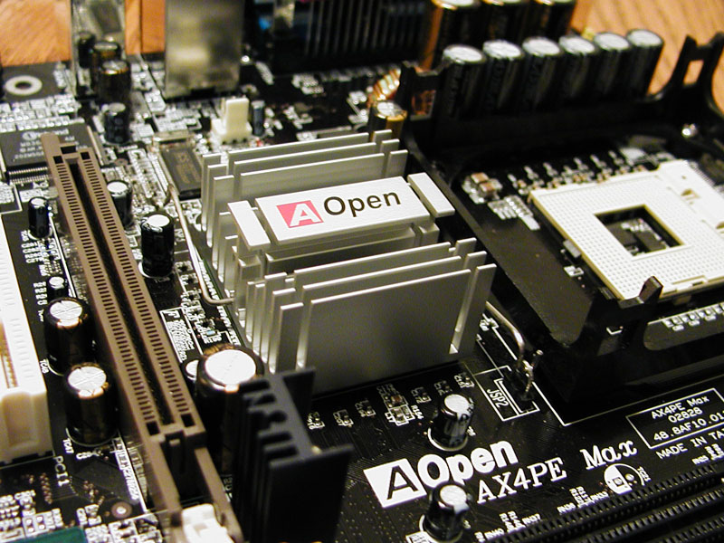
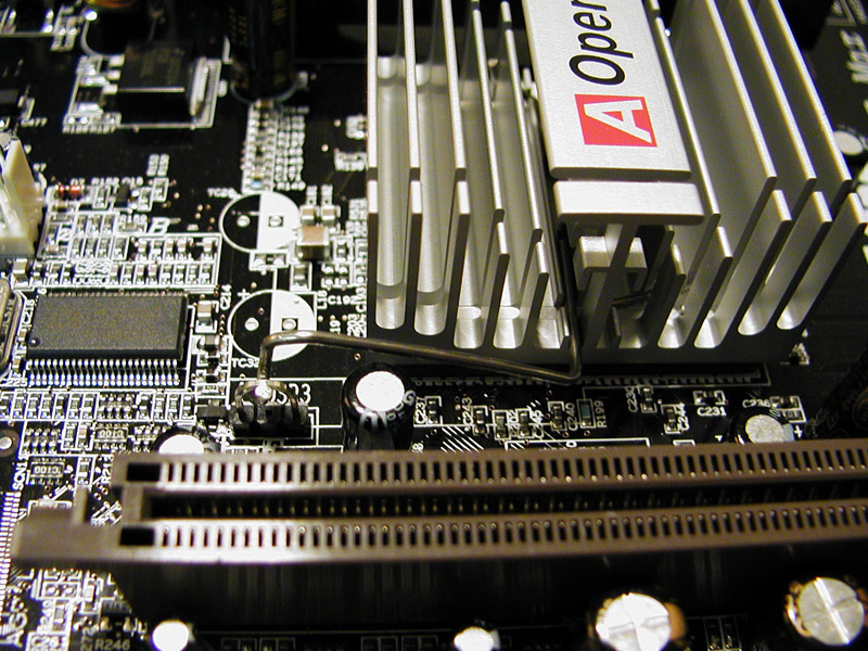
The board houses 3 DIMM sockets with no room between them and the AGP slot, meaning that most video cards should be removed when adding memory. You could easily break one of the plastic retention clips if left open while installing a video card.
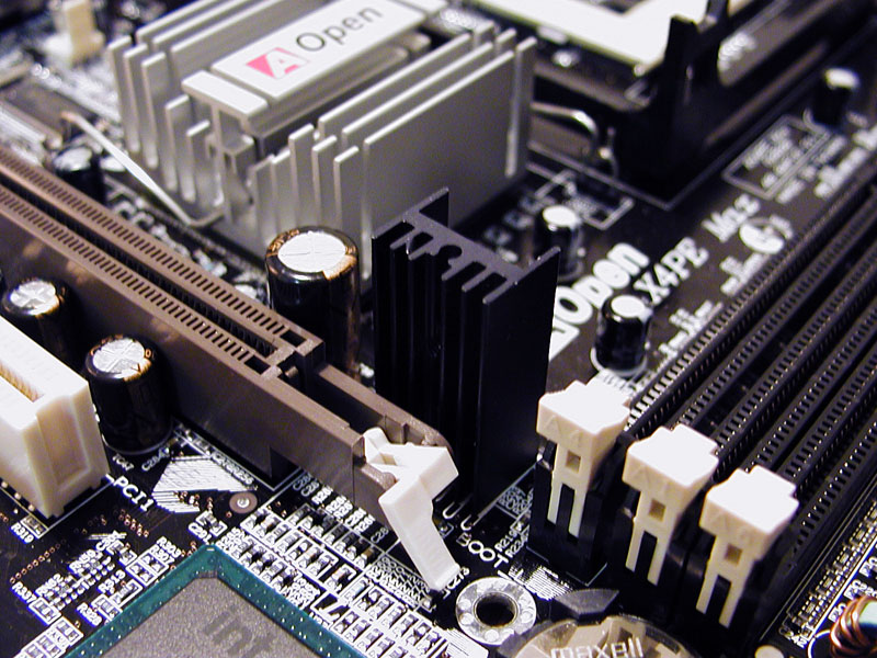
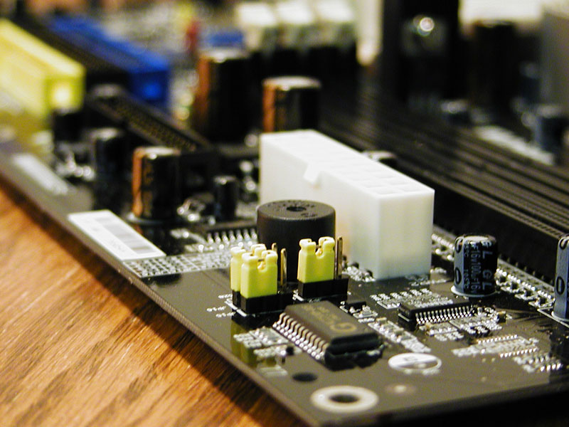
The main ATX connector for the board is located just below the last DIMM slot. It is out of the way and helps to increase ventilation. Below the ATX connector resides the board’s integreated speaker. Below this are two sets of jumpers that control the board’s Dr. Voice capabilities. Dr. Voice is a built-in diagnostic tool that actually speaks common motherboard problems through the speaker.
The boards’ three IDE headers are located just below PCI slots 1 thru 4, and the southbridge chip. They are different colors for easy identification, blue for IDE1, black for IDE2, and the third is ATA133 and colored yellow. Next to the IDE headers are two SATA connectors.
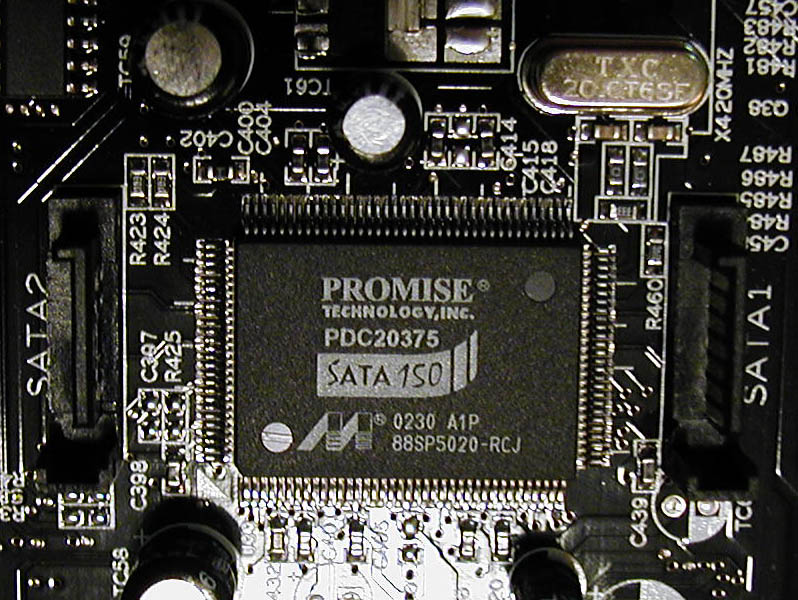
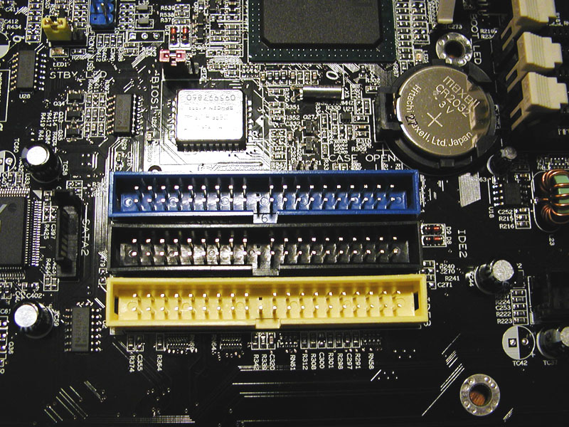
AOpen looks ahead to the future by offering Serial ATA RAID capability through the Promise PDC20375 controller, which is sandwiched between the two Serial ATA headers. This controller can support two independent Serial ATA devices, similar to the Silicon Image 3112 controller.
Below PCI slot 4 is the USB 2.0 header, as well as the BIOS restore jumper This jumper restores the hardwired BIOS to the settings stored within the user BIOS, through AOpen’s Die-Hard BIOS technology. Through the BIOS menu screens, you are able to backup a currently loaded BIOS to the board’s user BIOS for restoration at a later time. The CMOS clear jumper is located just above the board bios, between the USB 2.0 header and the southbridge chip. Along the edge of the board, you can see the System Fan 3 header and the 2 firewire headers (powered by Texas Instrument’s TSB43AB22 controller). Note that the SYSFAN3 header is not monitored by the Winbond W83627HF chip, but can be useful for powering a front or side case fan.
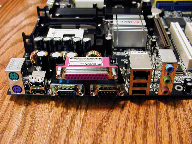
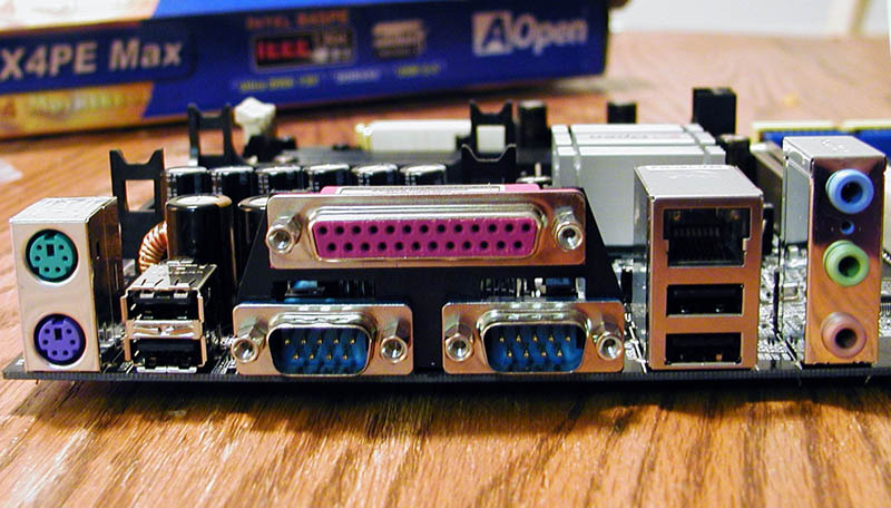
The rear panel contains no suprises. It is loaded with the standard set of ports: a keyboard and mouse port, 4 USB 2.0 ports, 2 serial ports, a parallel port, a 100Mbit Ethernet port, and 3 software configurable audio ports.
The manual states that the motherboard is jumperless, which is not accurate. It is true that there are no jumpers relating to any CPU settings, but there are numerous jumpers for such things as changing the Dr. Voice language (which can be set to English, Chinese, Japanese, and German), clearing CMOS, switching to the backup BIOS, and computer wakeup functionality
